How to integrating Dragino -NB and -CB series devices data with Thingseye
1. Introduction
This document guides you on integrating Dragino -NB and -CB series devices data with Thingseye.
The NB series devices end with the suffix -NB, and the CB series devices end with the suffix -CB. For example, S31B-NB is an NB device, and S31-CB is a CB device.
2. Prerequisites
To complete this tutorial, you need to have certificate files. lns1.thingseye.io is the Dragino's MQTT broker, which requires a CA certificate file, Certificate file, and the Private key file to use.
If customers need to use this MQTT connection with Thingseye, they need to contact the TE team to obtain three license files.

3. Creating Devices (Optional)
The following procedure is optional. If you haven't created any device in Thingseye first, Thingseye will automatically create a device for you based on the integration settings (the device name defined in the uplink decoder) just after it receives the first uplink from your device.Type your information message here.
First, you need to create devices in Thingseye to represent your physical devices. For example, you can name it Device A, and the second device could be Device B or any name you prefer. The device name should be unique within the Devices space.
In the left navigation, click Entities -> Devices.
Click the Add Device button (the button with the + sign), and from the dropdown menu, click Add new device.
In the Add new device dialog box, enter the device name in the Name text box. For example, we will use Device A.
Click the Add button.
Skip the connectivity testing by clicking the Close button.
The device is created and listed on the Devices page. Note that its initial state is Inactive because it has not received any data yet.
4. Data Converters
In Thingseye, Data Converters are components used to transform incoming or outgoing data between different formats, typically to convert raw telemetry data from devices into a structured format that Thingseye can understand, or vice versa.
4.1 Uplink
In the left navigation, click Integrations center, and then click Data converters.
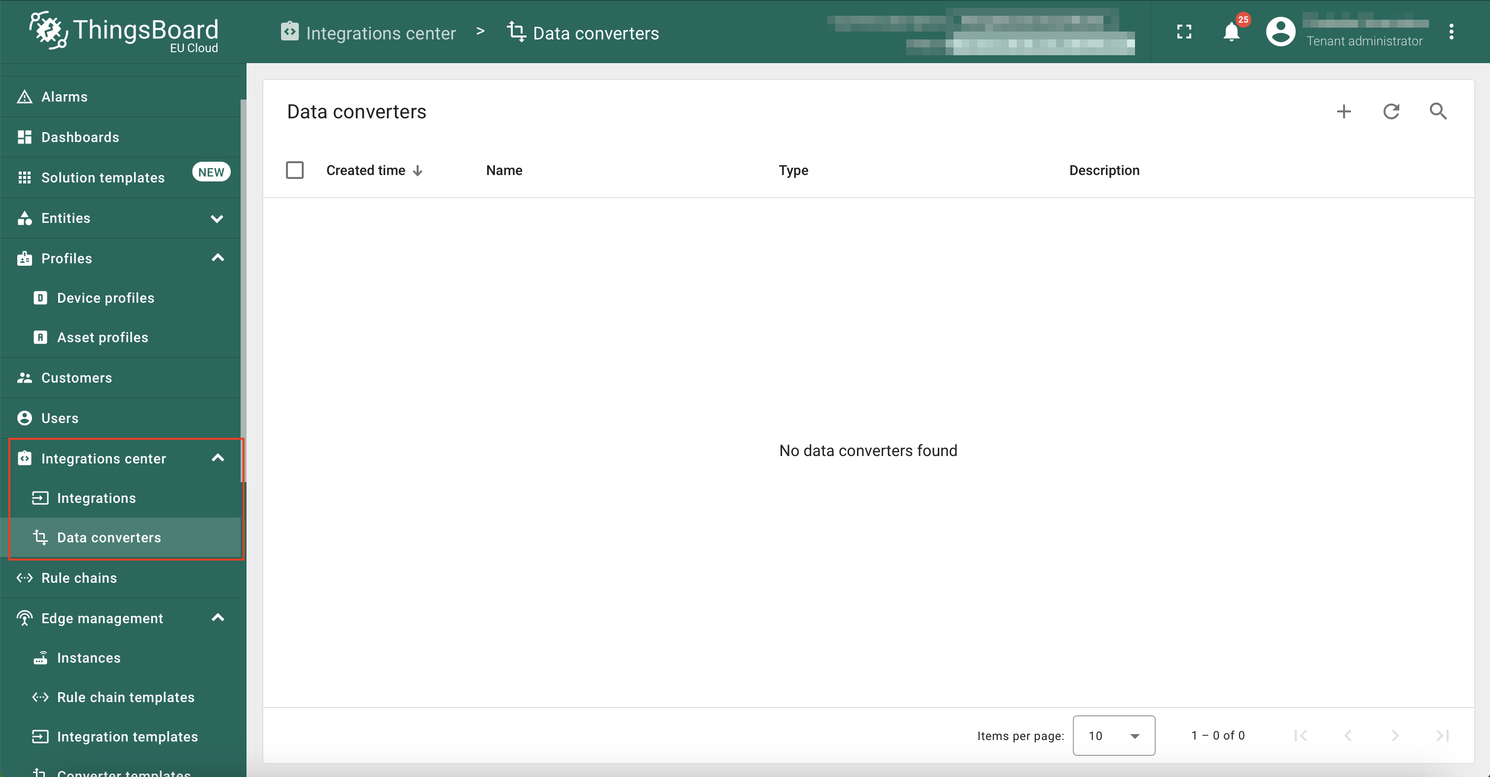
On the Data converters page, click on the ‘+’ button, and then click on the Create new converter from the dropdown menu.

The Add data converter window will appear.
Let's create an uplink data converter for the device named 'Device A'. Name it ‘MQTT Uplink Converter - Device A’ and select the Type as Uplink.
Click on the TBEL button if it has not been selected by default.
Modify the default TBEL function to match with your device as described below:
- Uncomment line 11:
var data = decodeToJson(payload)
- Line 13: Assign your device name to the deviceName field. - We used Device A as it is to match with our device, Device A in the Devices section.
- From line 38: Modify the telemetry section to allow parsed data to be assigned to the fields.
telemetry: {
temperature: data.temperature,
humidity: data.humidity,
rawData: payloadStr
}
The modified uplink decoder function to match with Device A is shown below.
// payload - array of bytes
// metadata - key/value object
/** Decoder **/
// decode payload to string
var payloadStr = decodeToString(payload);
// decode payload to JSON
var data = decodeToJson(payload);
var deviceName = 'Device A';
var deviceType = 'thermostat';
var customerName = 'Customer C';
var groupName = 'thermostat devices';
var manufacturer = 'Example corporation';
// use assetName and assetType instead of deviceName and deviceType
// to automatically create assets instead of devices.
// var assetName = 'Asset A';
// var assetType = 'building';
// Result object with device/asset attributes/telemetry data
var result = {
// Use deviceName and deviceType or assetName and assetType, but not both.
deviceName: deviceName,
deviceType: deviceType,
// assetName: assetName,
// assetType: assetType,
// customerName: customerName,
groupName: groupName,
attributes: {
model: 'Model A',
serialNumber: 'SN111',
integrationName: metadata['integrationName'],
manufacturer: manufacturer
},
telemetry: {
temperature: data.temperature,
humidity: data.humidity,
rawData: payloadStr
}
};
/** Helper functions 'decodeToString' and 'decodeToJson' are already built-in **/
return result;
Once you modify the decoder function, click on the Add button.

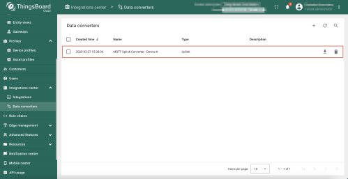
You should see that the newly added MQTT Uplink converter NB/CB is listed on the Data Converters page.
5. Add Integration
In the left navigation, click Integrations center, and then click Integrations.
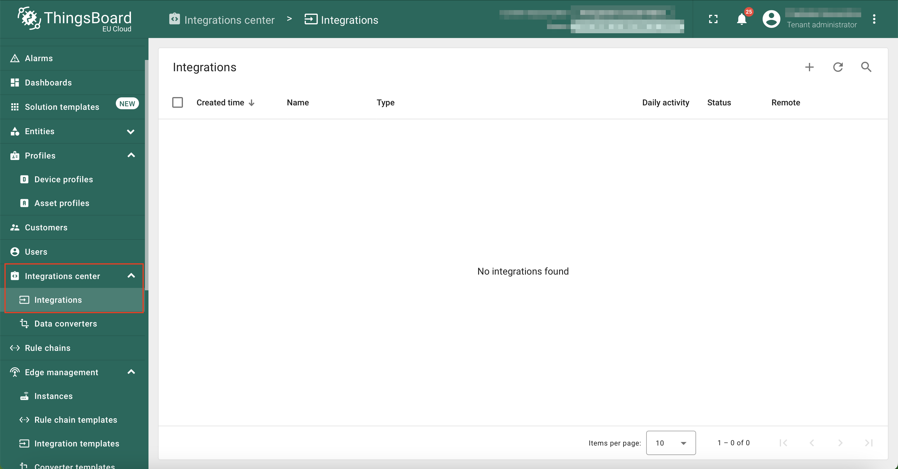
On the Integrations page, click on the '+' button.
The Add integration window appears.
In the Add integration window, configure the following settings:
Basic settings:
- Integration type: MQTT
- Name: MQTT integration - Device A
- Enable integration: YES
- Allows create devices or assets: YES
Click Next button.

Uplink data converter:
- Click on the Select existing button.
- Uplink data converter: Select MQTT Uplink Converter NB/CB from the dropdown list.
Click Next button.

Downlink data converter:
Dragino NB/CB devices don't require a downlink data converter to decode their payloads, so you can skip this step.
- Click on the Skip button in the Downlink data converter section.
Click Skip button.

Connection:
- Host: Host URL (Eg. 011731f7xxxxxxxxxxxfbbedfc63f4.s1.eu.hivemq.cloud)
- Port: 8883
- Credentials type: Basic
- Username: Username (from your HiveMQ Cloud Cluster with your credentials)
- Password: Password (from your HiveMQ Cloud Cluster with your credentials)
- Enable SSL: YES
- Topic: device/a (The topic can be anything; you can even use just the device name.)
- QoS: 0-At most once

Click on the Advanced settings button.
- Clean session: YES
- Retained: YES

Click on the Check connection button to verify the MQTT connection using the provided parameters.

If the connection is successful, you will see the Connected message. If not, check your connection parameters again.

Click on the Add button.
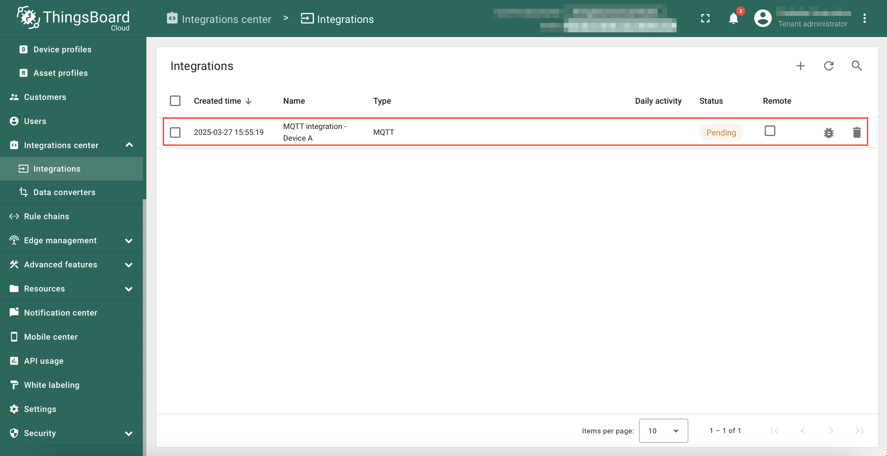
You should see that the newly added integration is listed on the Integrations page.
Since we haven't received data from a device yet, the integration Status is shown as Pending.
6. Verifying the receipt of data from virtual devices
6.1 How does it work?
We use the Mosquitto MQTT client to simulate MQTT messages, acting as a virtual device. First, install the Mosquitto client on your computer from this link. The Mosquitto client publishes messages to the MQTT broker (HiveMQ) on a specified MQTT topic.
The Mosquitto client publishes messages (payloads) on the topic /device/a. Of course, you can use any topic for testing.
The MQTT payload format is as follows:
Once Thingseye receives this message, it forwards this payload to the matching device through the integration.
5.2 Sending messages
On your computer's terminal, issue the following MQTT command which simulates the device 'Device A'. The message payload contains the fields IMEI, temperature, humidity, and pressure, which hold the values 350693903995577, 30, 80, and 1005 respectively. This payload is also (technically) known as telemetry.
If the integration was performed without errors, the status of the integration changes to 'Active' after the first telemetry transmission.

6.3 Viewing messages
Go back to the Integrations page.
Click on the MQTT integration NB/CB in the Integrations page to see its details.
Click on the Edit button (pen icon).
Click on the Disabled button in the upper-right corner.
Turn on the All messages (15 min) option. This will enable displaying all messages in the Events tab. This setting will expire in 15 minutes, and you will need to repeat the same steps if you want to view the messages in the Events tab later.
Click on the Apply button.
Then click on the Apply changes (tick icon) button.

Now go to the Events tab.
Select the Event type as Debug from the dropdown list.
Publish another message (of course, you can repeat the previous message by pressing the UP arrow on your keyboard and then press Enter key) to your MQTT broker from your terminal, for example:
mosquitto_pub -d -q 1 -h 011731f7928xxxxx.s1.eu.hivemq.cloud -p 8883 -u "xxxxx" -P "xxxxx" -t "device/a" -m '{"IMEI":"350693903995577", "temperature":30, "humidity":80, "pressure":1005}'
Now you can see that uplink message in the Events tab (Click the refresh button if you didn't see any messages in the Events tab). The status should be OK if there is no errors in your integration.

Then click on the three dots (...) in the Message column. You can see the uplink message's payload in the Message window.
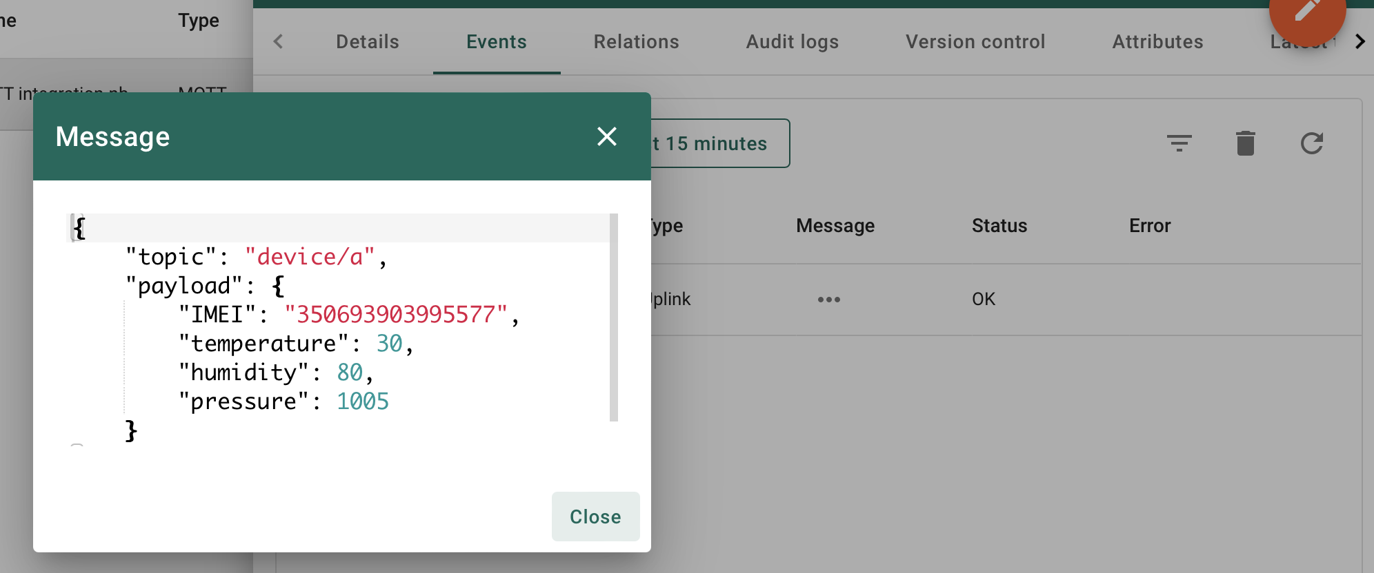
Now, you have successfully tested your integration with a simulated uplink payload and verified that it is received by Thingseye, and the device is provisioned.
7. Creating a Dashboard
Thingseye Dashboards provide a powerful way to visualize and monitor real-time and historical data from connected devices. They allow users to create interactive, customizable panels displaying telemetry data, device status, and other key metrics. With a variety of widgets, including charts, maps, and tables, dashboards help users gain insights, track trends, and manage IoT deployments efficiently.
This section guides you on how to create a dashboard to display temperature and humidity data from the device on a time-series chart. You may also use other widgets in Thingseye to display data according to your requirements.
First simulate a few messages using MQTT. This time, we have added the 'humidity' field to the payload. Eg:
In Thingseye, from the left navigation menu, click Dashboards. Then, click the + button and select Create new dashboard from the dropdown menu.
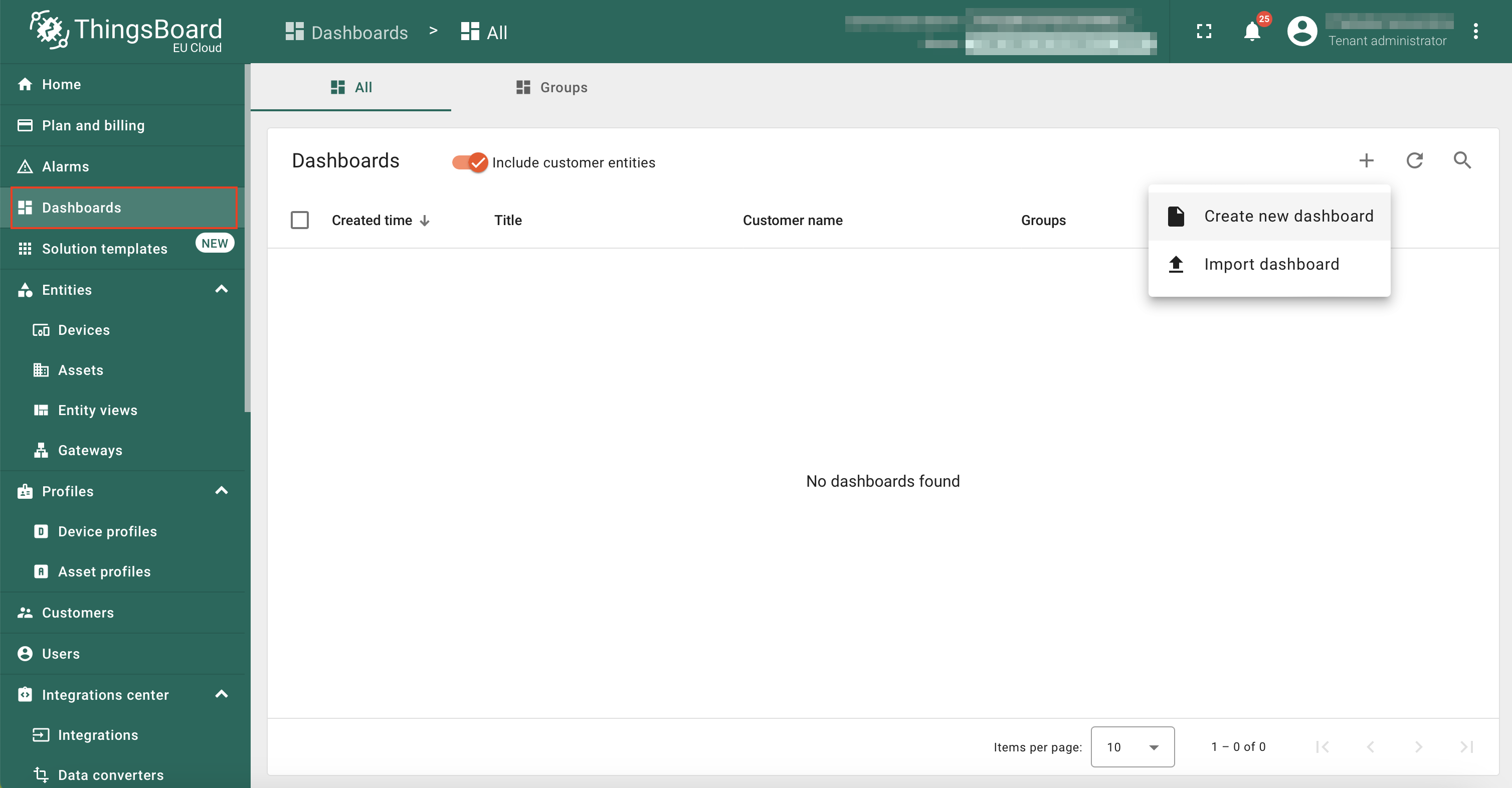
In the Title text box, enter NB/CB Test Dashboard as the title of the dashboard.
Click on the Add button.

Click on the Add widget / Add new widget button.

In the Select widgets bundle window, click Charts.

In the Charts: select widget window, click Time series chart.

Configure the Time series chart widget as follows:
- Datasource - select Device A device you provisioned.
- Series:
- temperature - you can see this key by default.
- humidity - Click Add series button. Then add the humidity for the key and then type % as its unit.
- Click on the Add button.

The time-series chart will appear in edit mode. Resize it by clicking and dragging the lower-right corner.
Click the Save button to add the widget to the dashboard.

Now send the following MQTT messages from the terminal to simulate the data.
mosquitto_pub -d -q 1 -h 011731f7928xxxxx.s1.eu.hivemq.cloud -p 8883 -u "xxxxx" -P "xxxxx" -t "device/a" -m '{"IMEI":"350693903995577", "temperature":27, "humidity":72, "pressure":1005}'
mosquitto_pub -d -q 1 -h 011731f7928xxxxx.s1.eu.hivemq.cloud -p 8883 -u "xxxxx" -P "xxxxx" -t "device/a" -m '{"IMEI":"350693903995577", "temperature":19, "humidity":80, "pressure":1005}'
The chart will update with the values in realtime, as shown in the below image.

8. Configure Physical NB-IoT Sensor
Now, let's experiment with sending data to Thingseye using a real NB-IoT device. For example, we will use the TS01-NB.
First, configure the NB-IoT device with the necessary MQTT settings using AT commands. Below is a list of AT commands you can use.
AT Commands
- AT+PRO=3,3 // Use MQTT to connect to Thingseye. Payload Type set to 3.
- AT+SUBTOPIC=<MQTT subscribe topic> Eg: TS01-NB
- AT+PUBTOPIC=<MQTT publish topic> Eg: TS01-NB
- AT+CLIENT=null
- AT+UNAME=<MQTT Username>
- AT+PWD=<MQTT Password>
- AT+SERVADDR=<Broker address, Port>
Test your uplink by pressing the ACT button for 1 second.
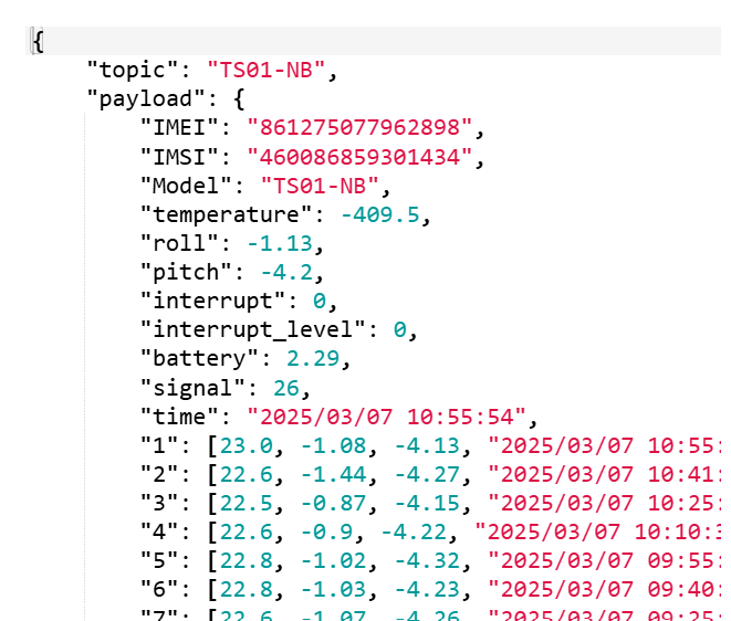
The following image shows the uplink payload of a real Dragino device. The publish topic is 'TS01-NB' that contains fields in the payload, IMEI, IMSI, Model, temperature, etc. Note that we have created a device named TS01-NB in the Devices section in advance.
