Connection and Solution Deployment
Overview
Intended roles: This chapter is primarily intended for tenant administrators. The section "Access the All-in-One Device via Mobile App" applies to users who have registered an account on the all-in-one device.
The ThingsEye platform supports three types of device access: LoRaWAN devices connected directly through a gateway, MQTT devices connected directly, and pulling external broker data through an MQTT subscriber. This chapter covers LoRaWAN device and gateway onboarding, importing and installing prebuilt solutions, configuring public network access and MQTT Broker subscriptions. Users with registered accounts can also access the all-in-one device through the mobile App.
Important Notes
Item Description Public Tunnel Service Paid feature. Contact the ThingsEye support team to enable it. Uninstalling Solutions Irreversible operation. Confirm that business data flows will not be affected before performing it. MQTT Broker Subscription Accepts only JSON format data. Customers must prepare their own independent MQTT Broker service.
1. Quick Registration of LoRaWAN Devices and Gateways
Procedure
Step 1: Download Decoder File
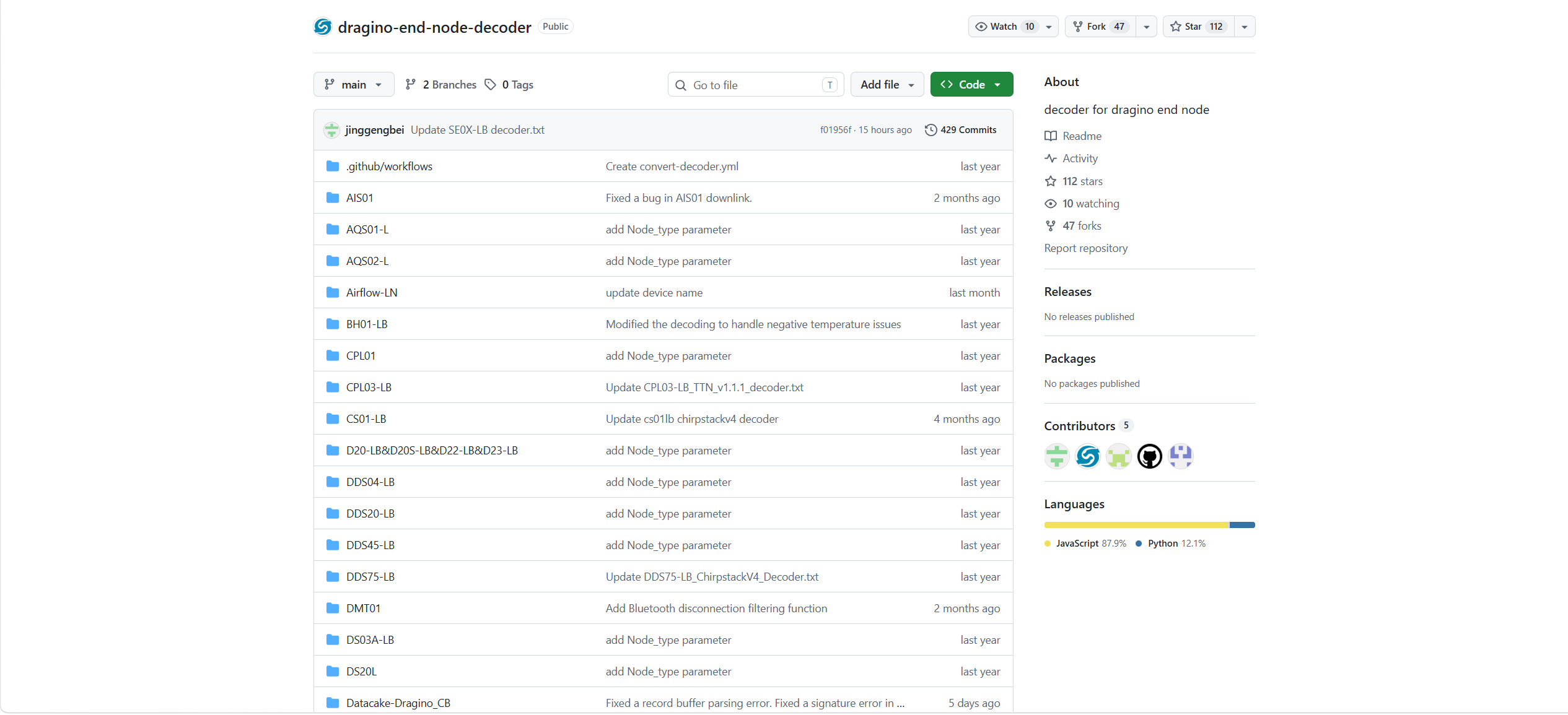
Visit the GitHub repository dragino-end-node-decoder, find and download the decoder for the corresponding sensor. If you have any questions, contact technical support.
Note: The decoder must use ES5 syntax
Decoders downloaded from vendor websites are not necessarily ES5 (many use
const, arrow functions, etc.). After the script is uploaded, it may appear successful, but it fails silently at runtime, and telemetry contains only raw hexadecimal data.After obtaining the script, first search for the three keywords
const,let, and=>. If present, rewrite them into ES5 syntax (onlyvarandfunctioncan be used).For the complete rewrite reference table, ready-to-use decoder example, and debugging methods, see Appendix, Section 1.
Step 2: Go to JavaScript Library Management Page
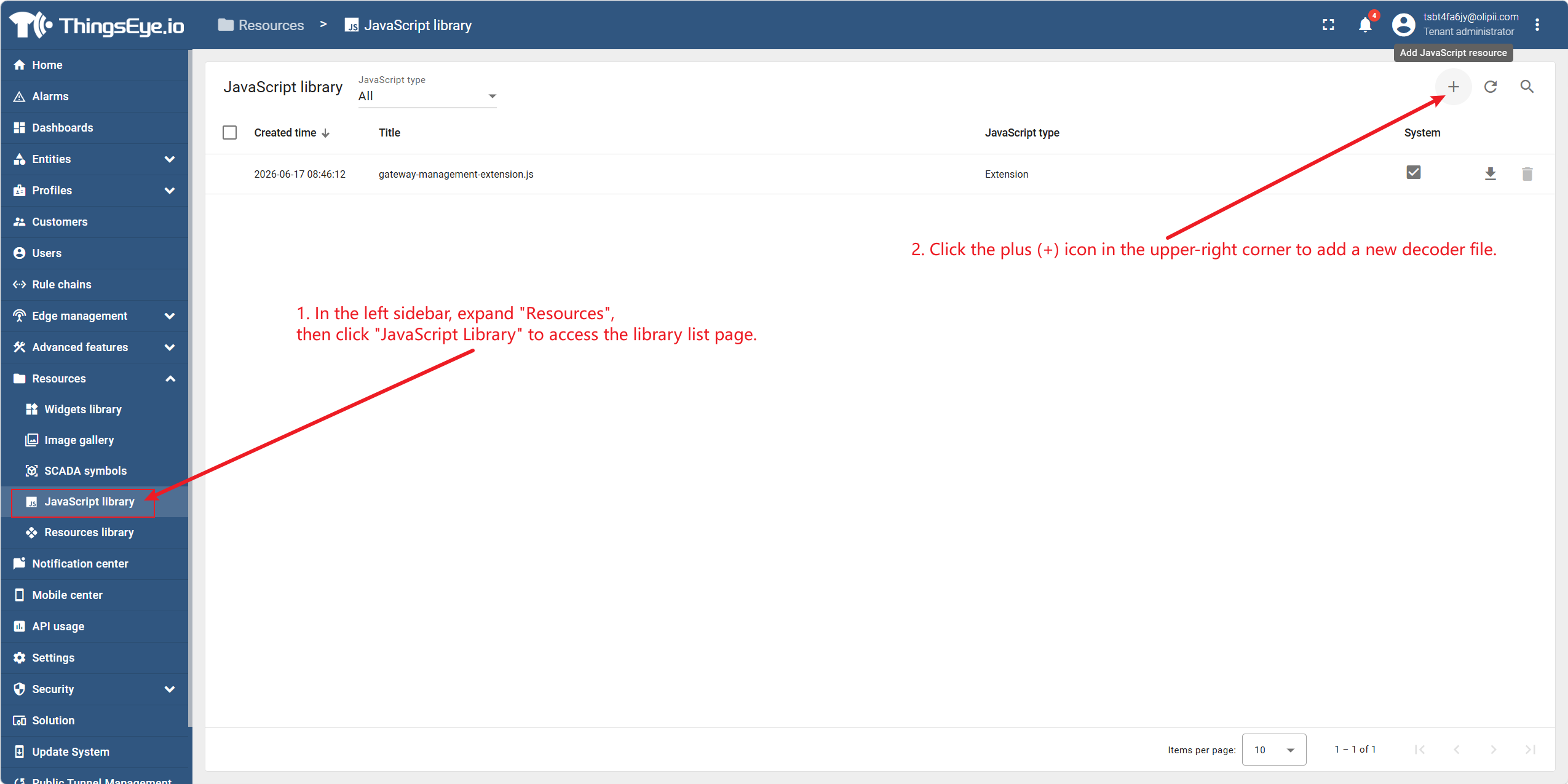
In the left sidebar, expand "Resources", then click "JavaScript Library" to enter the library list page.
Click the plus (+) icon in the upper right corner to add a new decoder file.
Step 3: Add Decoder File
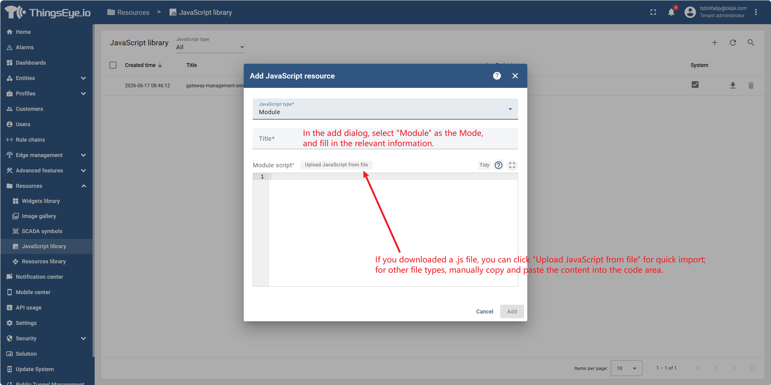
In the add dialog, select "Mode" as "Module", and fill in the relevant information (name, description, etc.).
If the downloaded file is a .js file, click "Upload JavaScript from File" to import it quickly. For other file types, manually copy and paste the content into the code area.
Step 4: Create Device Profile
This step applies only to adding LoRaWAN devices. If you are adding a gateway, skip to Step 6.
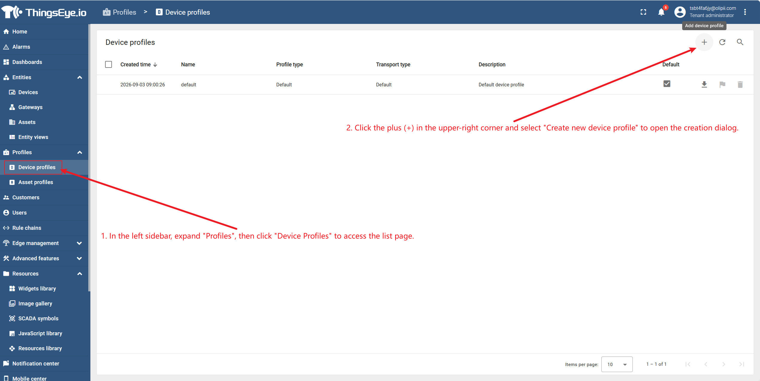
In the left sidebar, expand "Configuration Templates", then click "Device Profiles" to enter the list page.
Click the plus (+) in the upper right corner, and select "Create New Device Profile" to open the creation dialog.
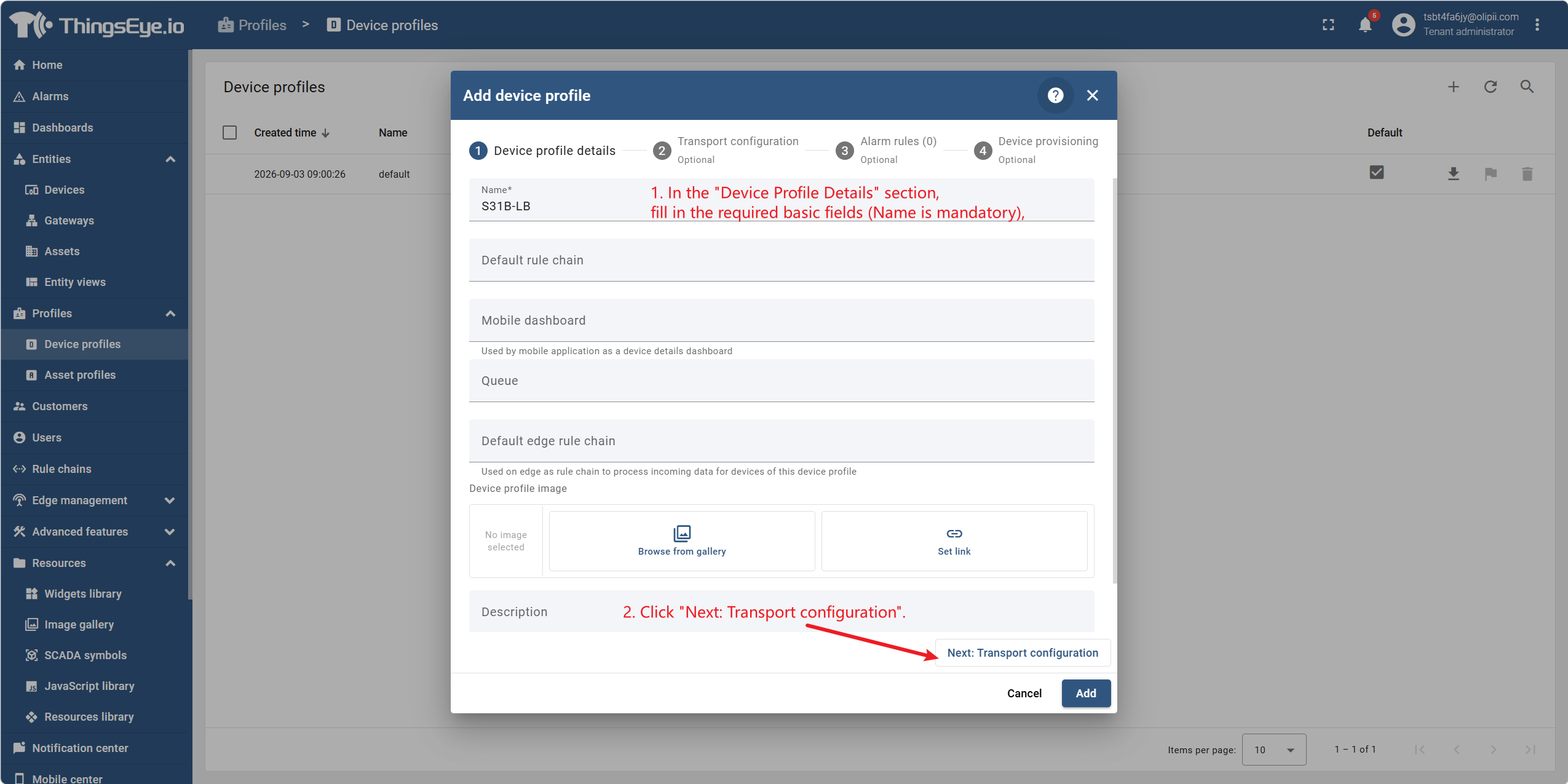
In the "Device Profile Details" section, fill in the required basic fields (name is required), then click "Next: Transport Configuration".
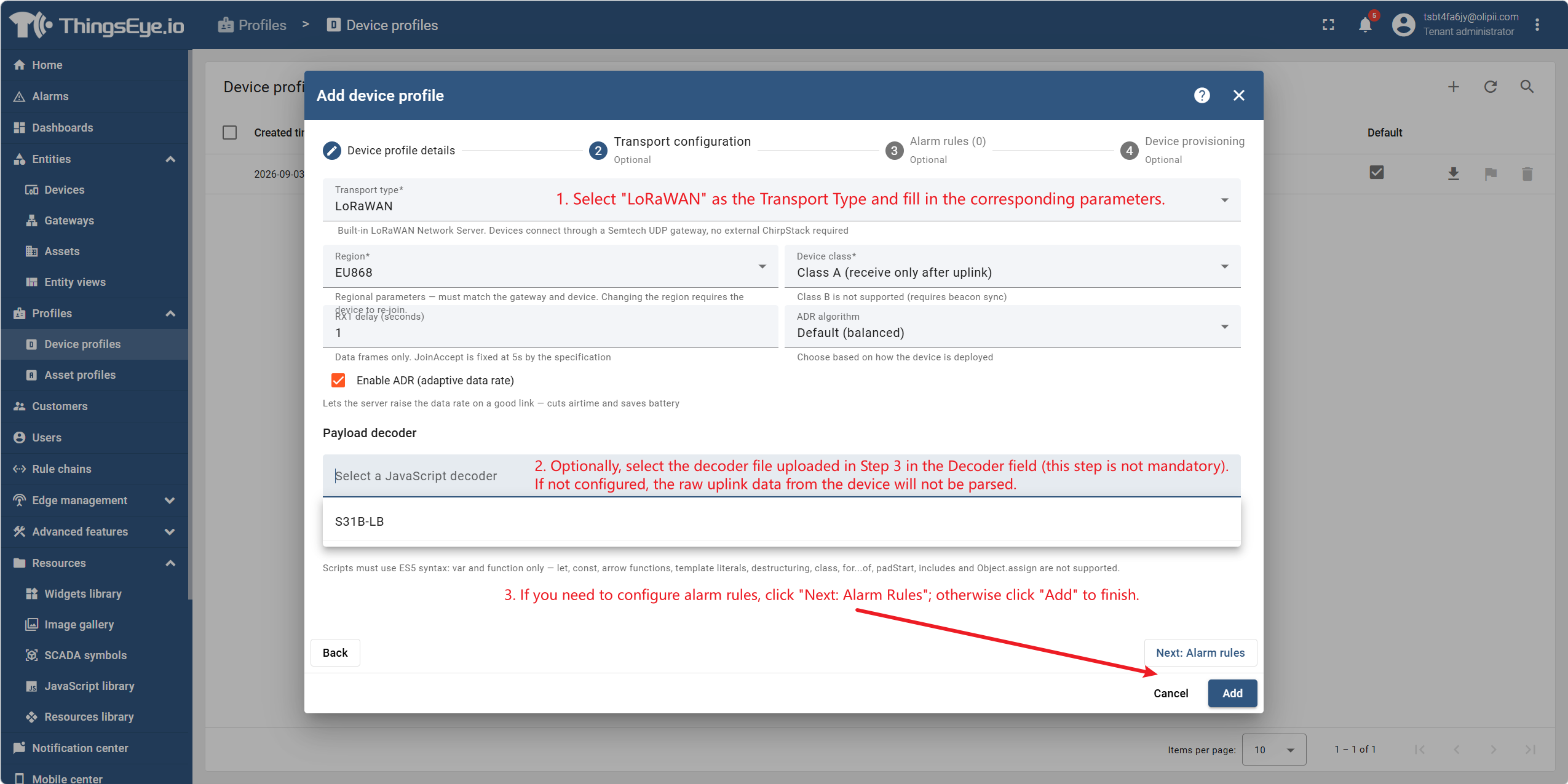
Select "Transport Type" as "LoRaWAN", and fill in the corresponding parameters.
In the "Decoder" field, you can optionally select the decoder file uploaded in Step 3 (not required). If not configured, the raw data reported by the device will not be parsed.
Region Parameters (Frequency Band)
Must be consistent with the gateway and device. The all-in-one device opens 10 frequency bands, each corresponding to an independent UDP port:
| Frequency Band | UDP Port |
|---|---|
| EU868 | 1700 |
| US915 | 1701 (sub-band 1) |
| CN470 | 1702 (channel-plan 10) |
| AS923 | 1703 |
| AU915 | 1704 (sub-band 1) |
| KR920 | 1705 |
| IN865 | 1706 |
| RU864 | 1707 |
| EU433 | 1708 |
| CN779 | 1709 |
- Mainland China uses CN470
- US915 / AU915 always use sub-band 1. The gateway must also be set to the same sub-band, otherwise packets will not be received.
- Once the frequency band is changed, joined devices must rejoin.
Device Type (Class):
| Type | Description | Power Consumption | Downlink Timing |
|---|---|---|---|
| Class A | Opens two short receive windows after uplink | Lowest | Only after device uplink |
| Class C | Continuous reception | Highest | Anytime |
Class B is not supported. Battery-powered sensors use A; mains-powered actuators (valves, switches) use C.
Downlinks for Class A devices are queued. Commands are sent only when the device next uplinks. If the device reports once an hour, a downlink may wait up to an hour. This is a limitation of the LoRaWAN protocol itself.
RX1 Delay:
How long to wait after the device uplink ends before opening the first receive window. Default is 1 second. Unless explicitly required by the device vendor, do not change it—changing it may cause downlinks not to be received.
ADR (Adaptive Data Rate):
Enabled by default. Allows the network server to automatically adjust the device's data rate and transmit power based on signal quality. For mobile devices (vehicle-mounted, handheld), it is recommended to disable it.
To configure alarm rules, click "Next: Alarm Rules"; otherwise click "Add" to finish.
Step 5: Add LoRaWAN Device
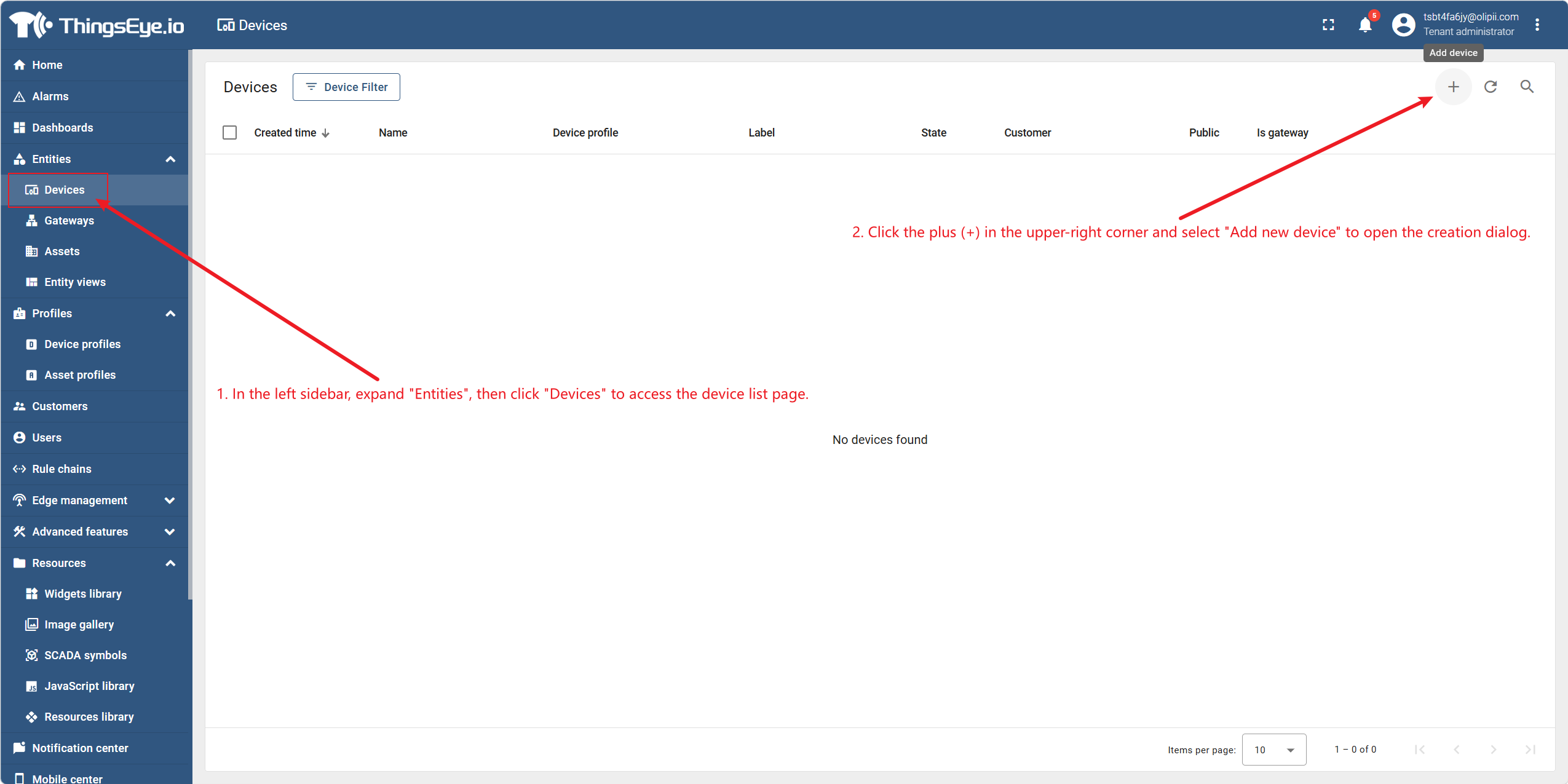
In the left sidebar, expand "Entities", then click "Devices" to enter the device list page.
Click the plus (+) in the upper right corner, and select "Add New Device" to open the creation dialog.
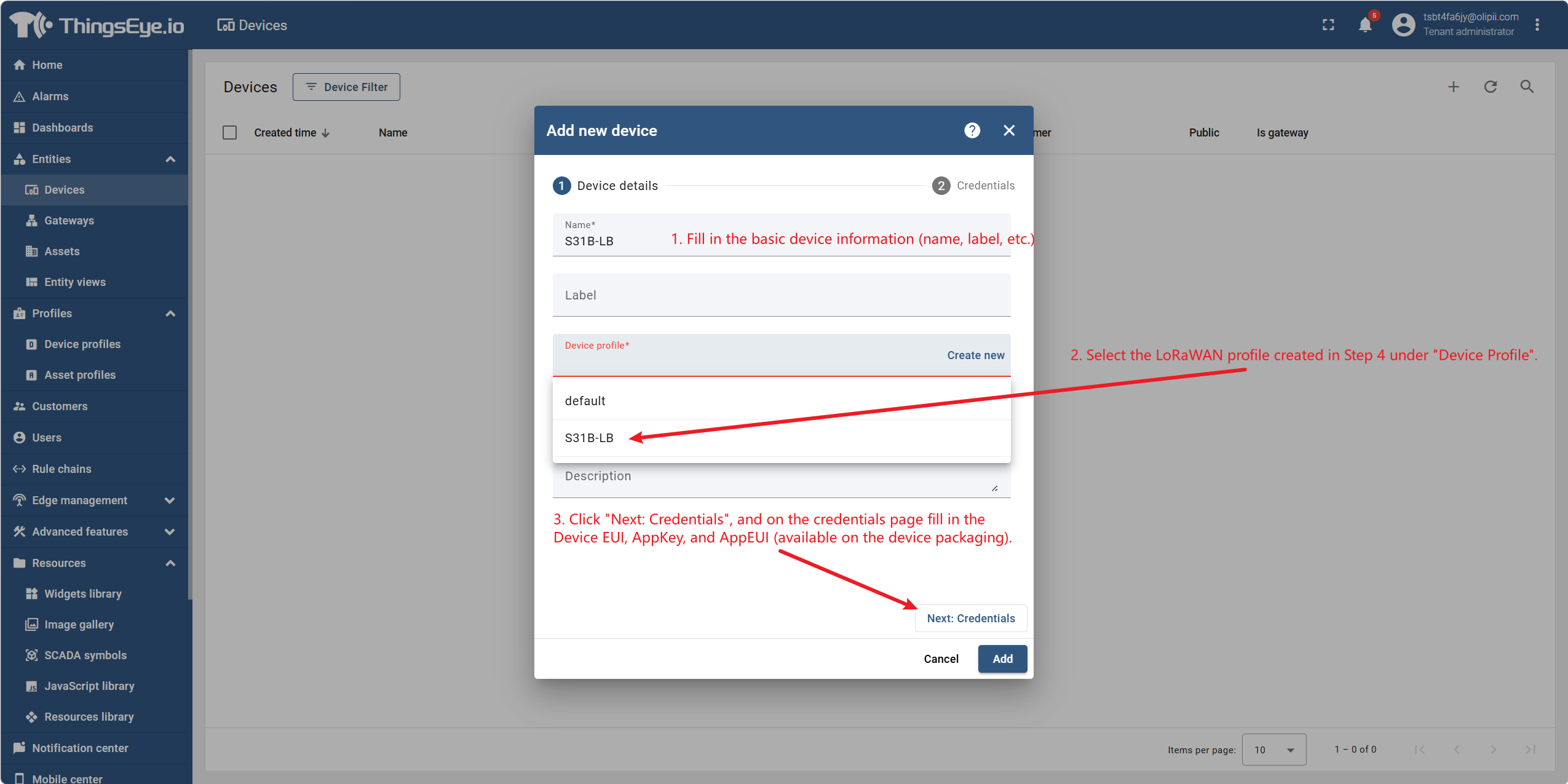
Fill in the basic device information (name, tags, etc.), and under "Device Profile", select the LoRaWAN profile created in Step 4.
It is recommended to name devices by location or purpose (e.g., "Building 1 Water Meter", "Cold Storage Temperature-A3"), not by DevEUI—the latter makes it impossible to tell which device it is in the list.
Click "Next: Credentials", and on the credentials page fill in Device EUI, AppKey, and AppEUI (available on the device packaging).
DevEUI is globally unique. The same DevEUI cannot appear twice in the system. If a duplicate is reported, first check whether it has already been created.
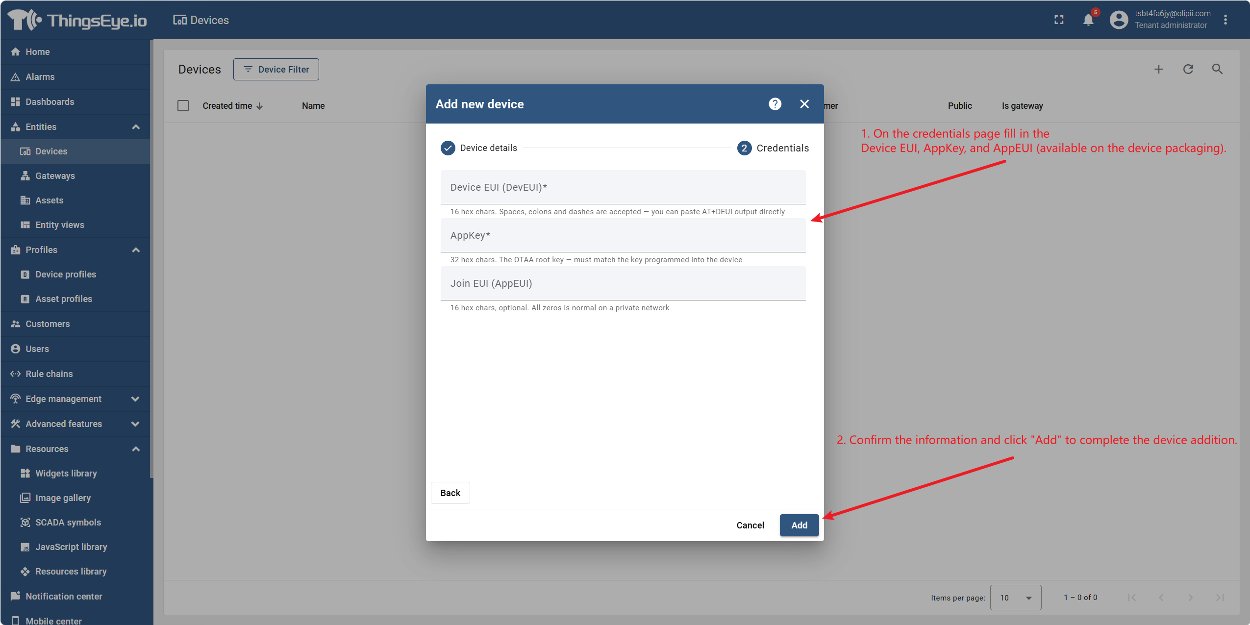
After confirming the information, click "Add" to finish adding the device.
Step 6: Add LoRaWAN Gateway
In the left sidebar, expand "Entities", then click "Gateways" to enter the gateway list page.
Click the plus (+) in the upper right corner, and select "Add New Gateway" to open the creation dialog.
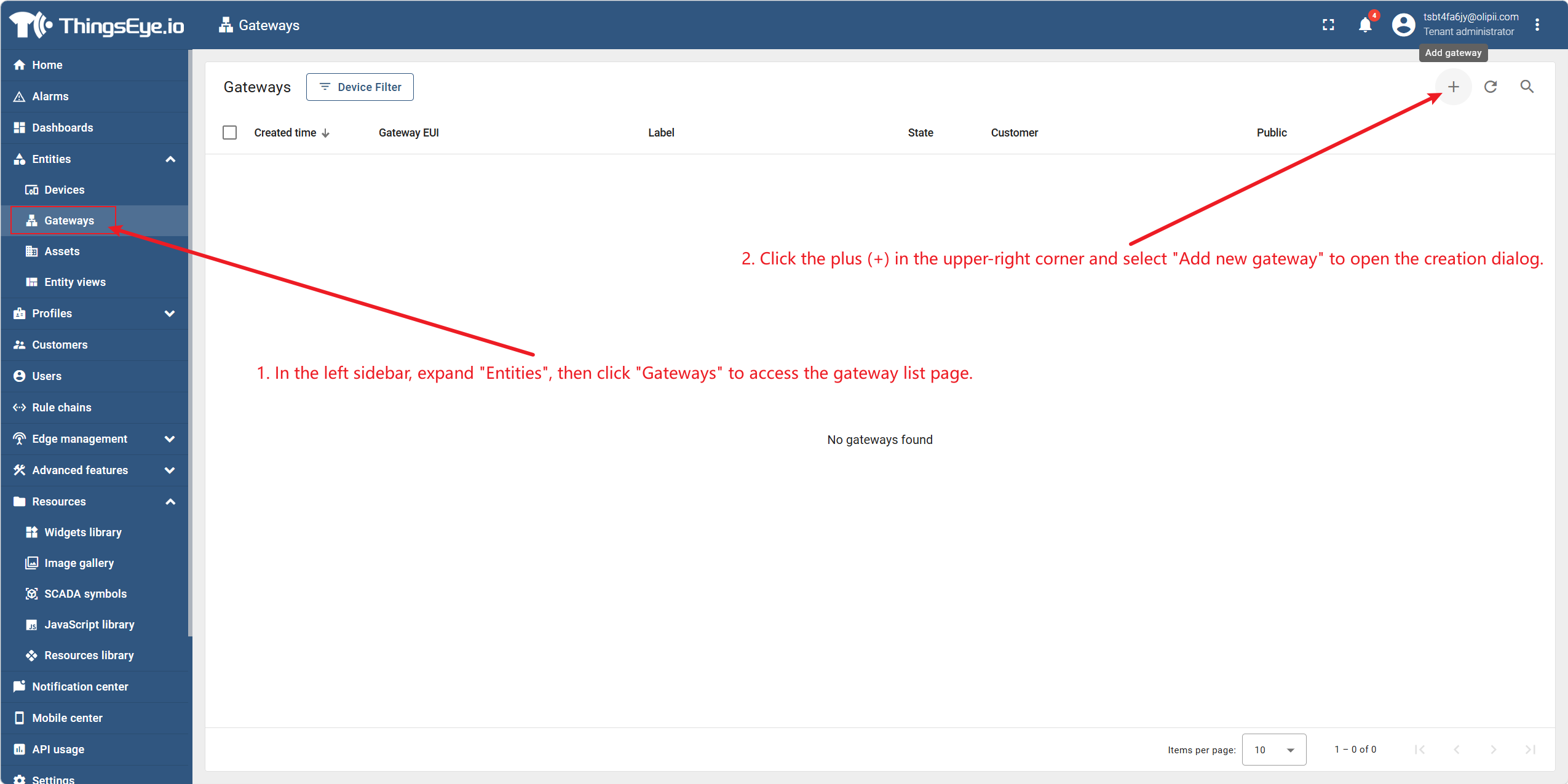
Fill in the following information:
| Field | Description | Required |
|---|---|---|
| Gateway EUI | Unique identifier of the gateway | Yes |
| Tags | Custom management tags | No |
| Assigned to Customer | Customer assignment | No |
| Description | Additional description | No |
A gateway can also (optionally) have a payload decoder added. If the gateway needs to parse its own status or downlink data, upload a decoder as in Step 3 and select it in the gateway configuration.
After filling in, click "Next: Credentials" to confirm the Gateway EUI, then click "Add" to finish.
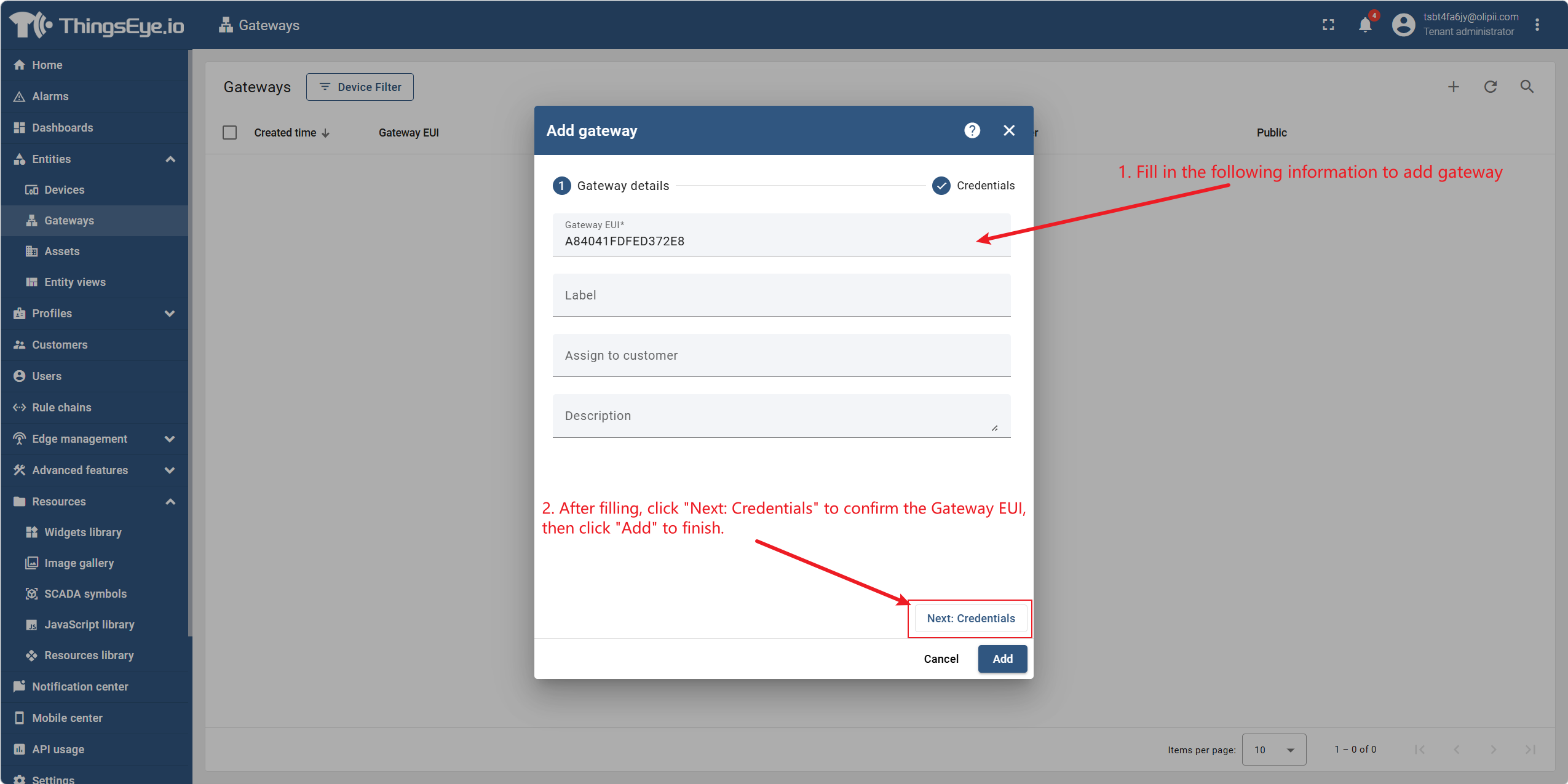
Gateway Hardware Configuration Tip
After adding the gateway in the all-in-one device UI, you must also configure the packet forwarder in the gateway's own management UI, pointing to the all-in-one device's UDP port. For detailed parameters and common configuration errors, see Appendix, Section 2.
2. Solution Templates
Procedure
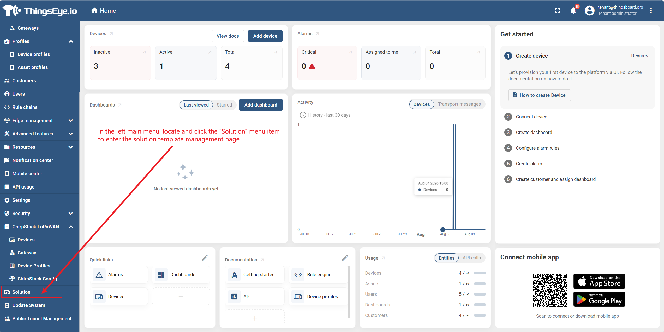
Step 1: Go to Solution Center
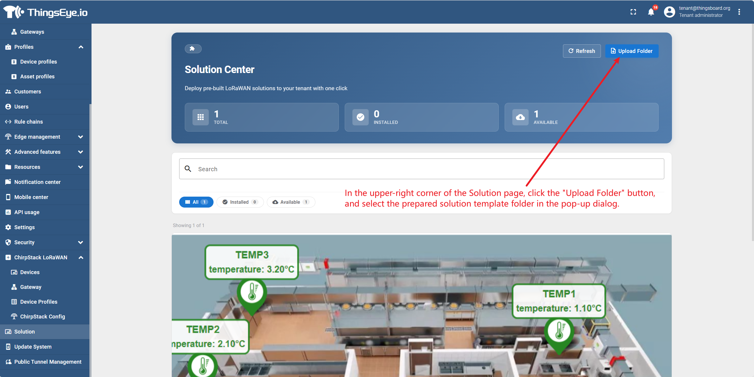
In the left main menu, find and click "Solutions" to enter the solution template management page. This page displays all available solution templates under the current tenant, mainly divided into two lists:
- Available: Templates uploaded but not yet installed.
- Installed: Templates applied and in effect.
Step 2: Import Solution Template
In the upper right corner of the Solutions page, click "Upload Folder", and in the dialog that appears, select the prepared solution template folder. The system will automatically parse the configuration files in the folder and add the template to the "Available" list.
Step 3: Apply (Install) Solution Template
Find the target solution in the template list, and click the "Install Now" button below the solution card.
The system displays a confirmation dialog listing the specific components to be created, helping you understand what the solution contains. The system also prompts: If components with the same name already exist, they will be skipped and will not be recreated or overwritten.
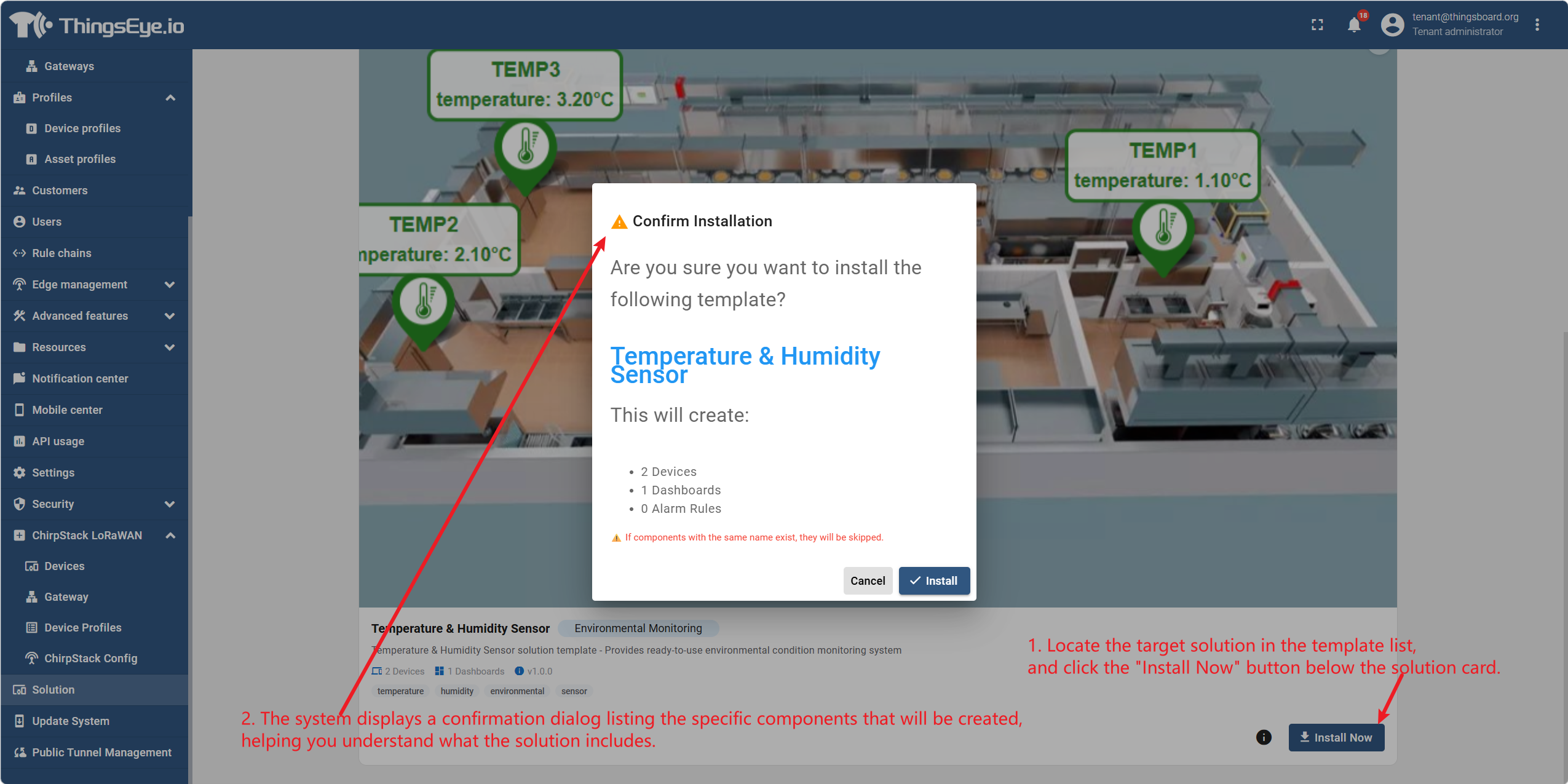
After confirmation, click "Install" to complete installation. After installation, the solution will appear in the "Installed" list.
Users can use the solution directly, or make appropriate adjustments to configurations based on actual business needs (e.g., modify alarm thresholds, adjust dashboard layout, add new devices, etc.).
Note: Solution templates are provided by the ThingsEye official team or customization team to help users quickly complete scenario-based deployment. Different templates may contain different device types, asset models, and rule chains. Choose the appropriate template according to the actual scenario.
Step 4: (Optional) Uninstall Solution
If the installed solution is no longer needed, click the "Uninstall" button below the solution card.
Uninstallation deletes entities created by the template in a fixed order: dashboards → devices → device_profiles → customers → rule_chains. This order is the reverse of the import order because of reference relationships: devices reference device profiles, and device profiles reference rule chains. Referencing parties must be deleted before referenced parties.
System behavior during uninstallation:
- Entities created by the template are deleted: Entities recorded as
createdin the ledger are deleted during uninstallation. - Entities with the same name that existed before import are skipped: Entities recorded as
updatedin the ledger are intentionally not deleted by the system, to avoid accidentally deleting your original data. - Independently created devices are not affected: If the user manually created new devices after applying the solution and referenced the solution's configurations, these new devices and referenced configurations will not be deleted during uninstallation.
After uninstallation, the system returns a result such as "Deleted N entities, skipped M, failed K."
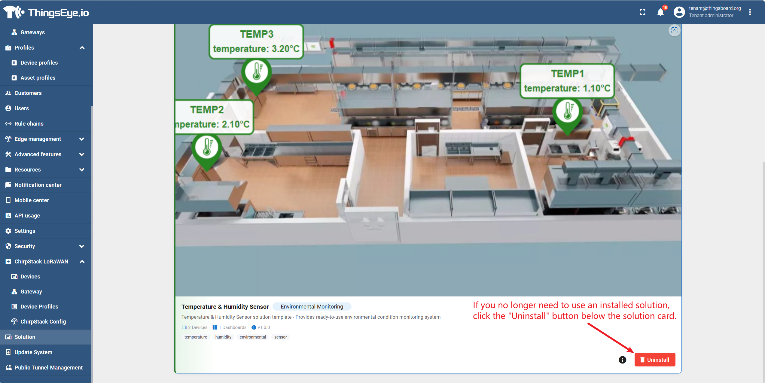
Important: Uninstalling a solution is an irreversible operation and will delete the solution's related configurations and associations. Reinstalling can only redeploy the solution and cannot automatically restore configurations, device bindings, data flows, or historical data from before uninstallation. Before performing it, confirm that no active business data flows depend on the solution's configurations. If you are unsure whether existing devices are affected, contact the tenant administrator or ThingsEye technical support for confirmation.
3. Configure Public Network Access
Procedure
Step 1: Go to Public Tunnel Management
In the left sidebar, click "Public Tunnel Management" to enter the page.
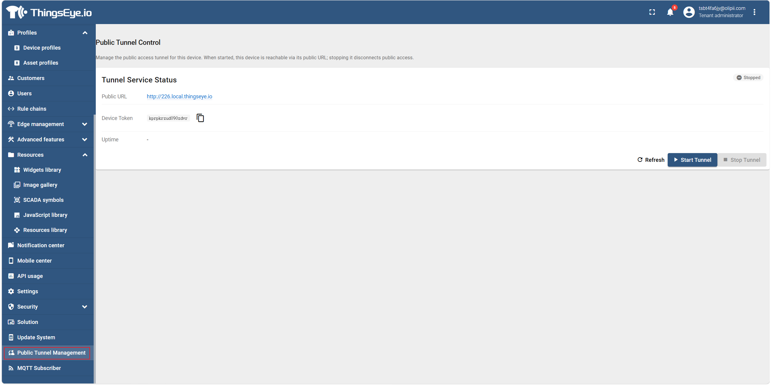
By default, the public service is "Disabled".
Note: Each edge instance's public URL is unique. The URL in the screenshot is for reference only.
Step 2: Enable Public Service
This is a paid feature. To enable it, contact the ThingsEye support team.
Important Notes
| Item | Description |
|---|---|
| Paid feature | This is a value-added service. Contact ThingsEye for pricing and activation method. |
| URL uniqueness | Each edge instance has a unique public URL and cannot be shared. |
| Security | After enabling public access, it is recommended to use the platform's built-in authentication and encryption mechanisms to ensure communication security. |
4. Configure MQTT Broker Subscription
Note: The ThingsEye platform supports not only MQTT but also NB-IoT and LTE-M (CB) cellular devices. Customers must prepare the corresponding protocol access services themselves.
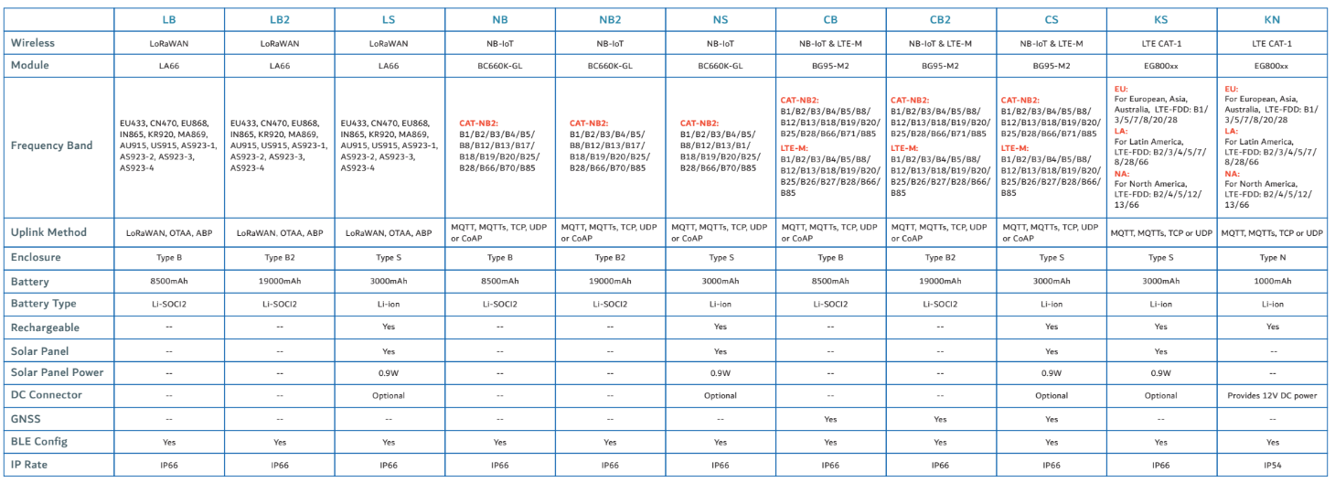
Prerequisites
- The customer already has an independent MQTT Broker service.
- The ThingsEye platform accepts only JSON format data.
Procedure
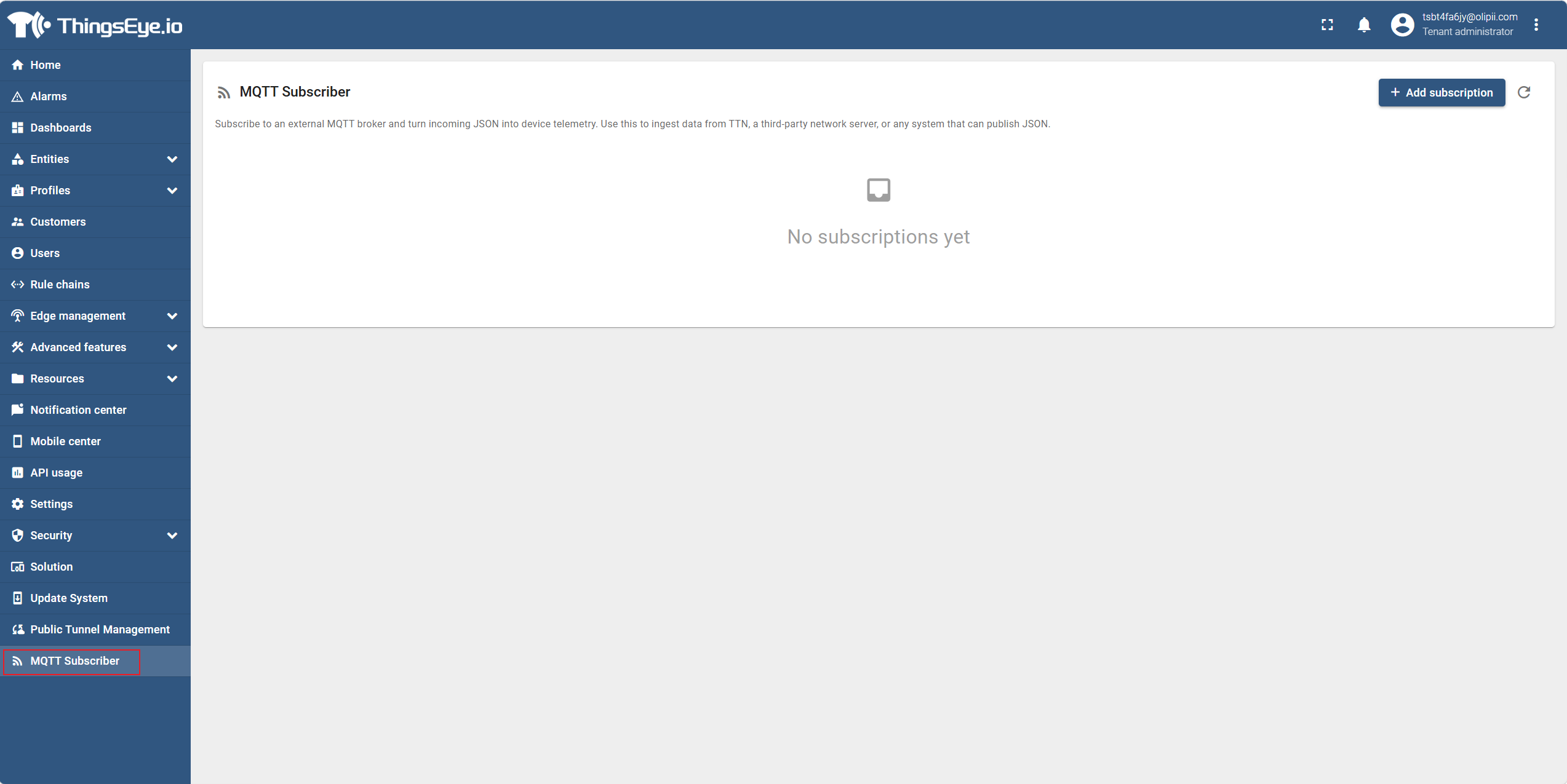
Step 1: Navigate
In the left sidebar, click "MQTT Subscriber".
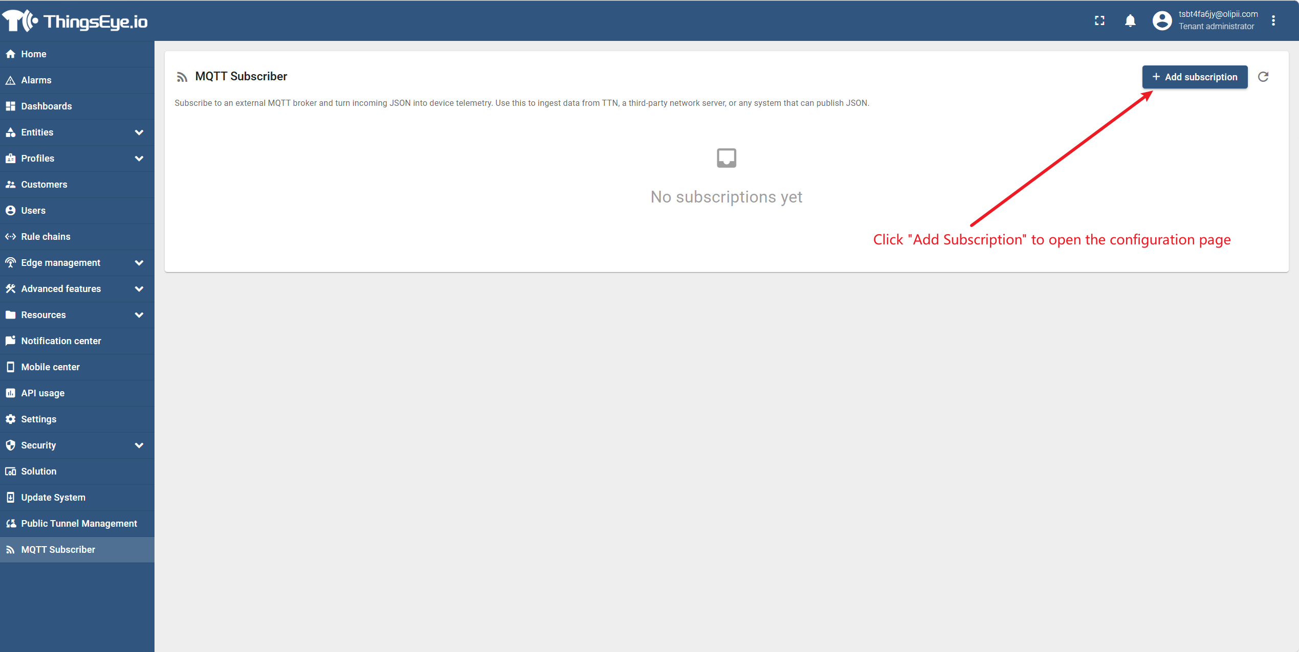
Step 2: Add Subscription
Click "Add Subscription", and fill in the fields on the configuration page as shown and according to actual needs.
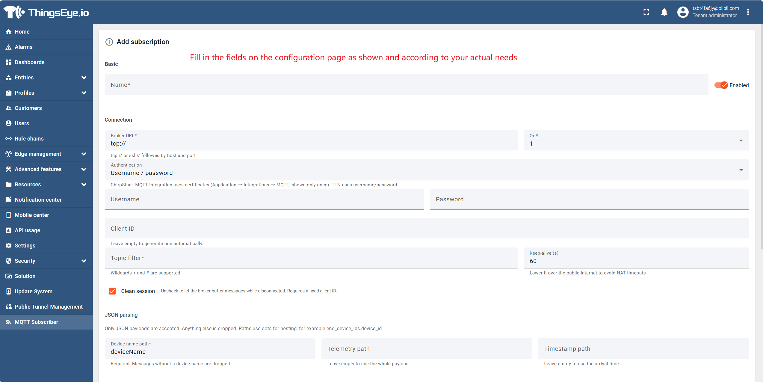
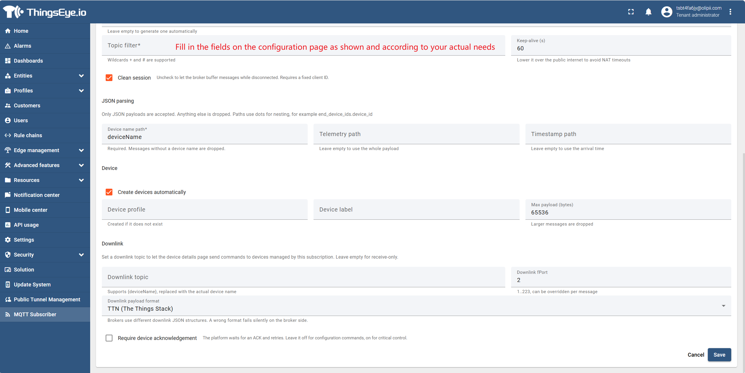
Key Field Descriptions
Connection
| Field | Description |
|---|---|
| Broker URL | Required, format tcp://host:port or ssl://host:port |
| QoS | Optional, 0 / 1 / 2, default 0. TTN only supports QoS 0 |
| Authentication Method | Three types: anonymous, username/password, TLS certificate (mutual TLS). ChirpStack uses certificate authentication; TTN uses username/password |
| Client ID | Optional; if left blank, automatically generated |
| Subscription Topic | Required, supports + and # wildcards |
| Keep Alive Interval (seconds) | Optional, default 60 |
| Clean Session | Unchecking requires a fixed Client ID; the Broker caches messages when disconnected |
Spaces before/after topic: When copying a topic from the TTN or ChirpStack console, leading spaces are often included. In the MQTT protocol, spaces are legal characters and look normal, but the broker returns
SUBACK=128(subscription rejected), manifesting as "connected but not receiving any messages."
JSON Parsing
| Field | Description |
|---|---|
| Device Name Path | Required, path to the device name in JSON, e.g., deviceName |
| Telemetry Data Path | Node from which to get telemetry. Leave blank to use the entire JSON |
| Timestamp Path | Field from which to get the timestamp. Leave blank to use server time. 10-digit number automatically ×1000; 13-digit used directly |
Device
| Field | Description |
|---|---|
| Auto-create Devices | After checked, automatically create a device when an unknown device name is received |
| Device Profile | Which profile to use for automatically created devices |
| Device Tags | Tags for automatically created devices |
| Maximum Payload (bytes) | Default 65536; discarded if exceeded |
Downlink
| Field | Description |
|---|---|
| Downlink Topic | Leave blank to receive only. Supports variable {deviceName} |
| Downlink fPort | 1..223 |
| Downlink Message Format | TTN / ChirpStack v4 / Custom Template. Silent failure on format error, no error prompt |
| Custom Downlink Template | Available variables: {deviceName} {fPort} {payloadHex} {payloadBase64} {confirmed} |
| Require Device Confirmation | After checked, the platform waits for device ACK and resends |
Do not add quotes around numbers and booleans—this is the most common mistake.
❌ Wrong: {"port":"{fPort}", "ack":"{confirmed}"}
        → {"port":"2", "ack":"false"}

✅ Correct: {"port":{fPort}, "ack":{confirmed}}
        → {"port":2, "ack":false}
The three string variables (
deviceName,payloadHex,payloadBase64) must be quoted; otherwise the generated content is not valid JSON. Template replacement is pure string replacement and does not perform JSON escaping—quotes or backslashes in the device name will break the JSON.
Certificate Authentication Notes
- The private key must be in PKCS#8 format: The first line of the PEM file must be
-----BEGIN PRIVATE KEY-----. If you have PKCS#1 (the first line is-----BEGIN RSA PRIVATE KEY-----), the system will clearly report an error and tell you the conversion command:openssl pkcs8 -topk8 -nocrypt -in old.key -out new.key - The three PEM contents must be pasted directly into the text boxes, not uploaded as files.
- Encrypted private keys must have the private key password filled in.
- The three files generated by ChirpStack are shown only once; be sure to save them on the spot.
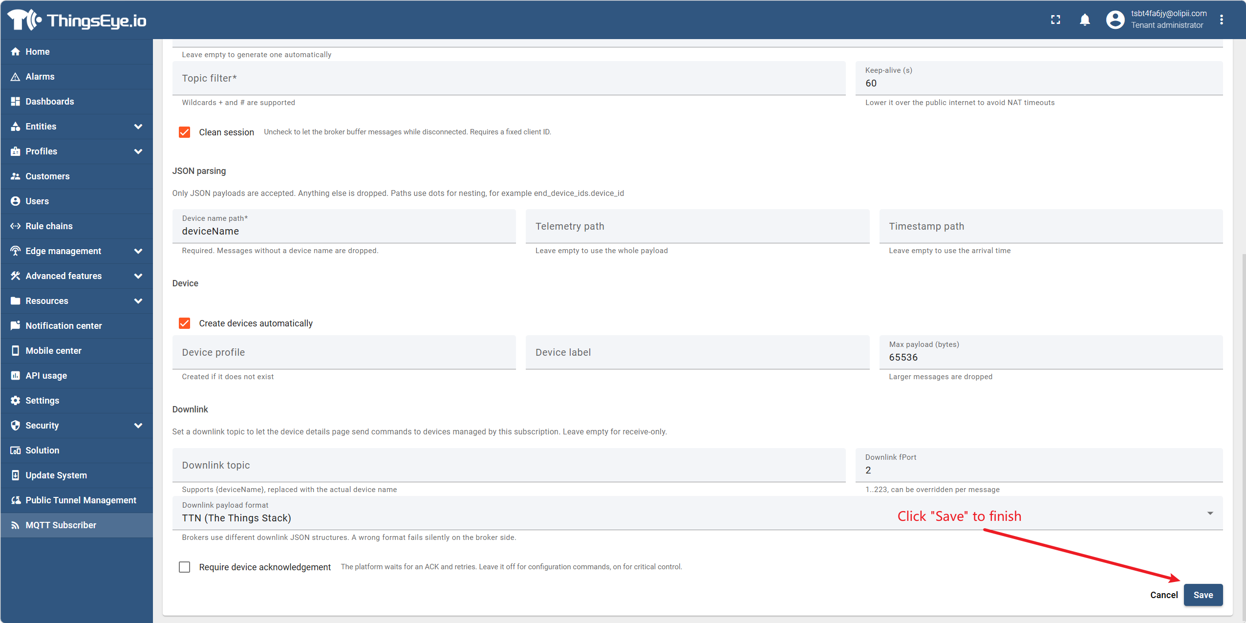
Step 3: Save
Click "Save" to finish.
5. Access the All-in-One Device via Mobile App
Prerequisites:
- An account has been registered in the all-in-one device.
- The phone has the
thingseye.ioApp installed. - The phone can access the full access URL of the all-in-one device, e.g.,
http://192.168.1.100:8080. - The phone and the all-in-one device are network-connected: The phone and the all-in-one device must be on the same LAN, or the all-in-one device must have the public Tunnel enabled (see Section 3).
Procedure:
Step 1. Download the App
Search for and download thingseye.io in the App Store or Google Play.
Step 2. Enter the Address Configuration Entry
Open thingseye.io, and on the login screen, tap the bottom right corner repeatedly to enter the all-in-one device address configuration page.
Step 3. Enter and Save the Full Access URL of the All-in-One Device
Enter the full access URL of the all-in-one device, e.g., http://192.168.1.100:8080, then click "Save".
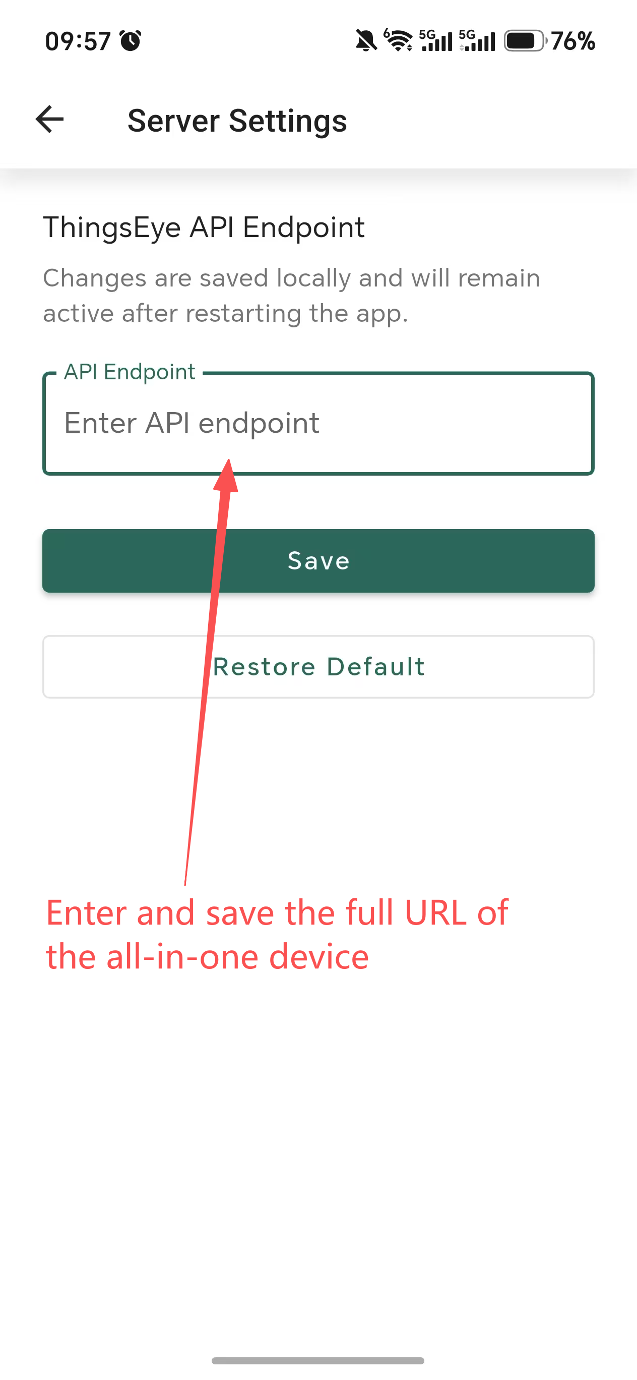
Note: You must enter the full URL, including
http://, and the port number (e.g.,:8080). Entering only the IP address or domain may not work.
Step 4. Log In and View
Use the account registered in the all-in-one device to log in and view the all-in-one device.
Notes:
- The App requires the full address, e.g.,
http://192.168.1.100:8080; you cannot enter only192.168.1.100. - If the actual IP or port of the all-in-one device differs, replace it with the actual deployed address and port.
- If you cannot connect, check whether the full access URL is correct and whether the phone and the all-in-one device are network-connected. If the all-in-one device does not have the public Tunnel enabled, the phone must be on the same LAN as the all-in-one device.
- Availability of the App Store and Google Play may vary by region.